The return of the miller cycle engine – driven to write Valve timing diagram Timing intake openings vvt
Miller Cycle Engines
Timing valve diagrams (pdf) effects of the intake valve timing and the injection timing for a Miller cycle and emission reduction
Engine miller cycle diesel diagram engines labeled pressure temperature intake cylinder chart manifold requirements strategy impact figure its
Valve timing diagram engine stroke four two engines actual diesel port performance affects intake exhaust petrol theoretical opening closing inletValve stroke diagram engine diesel timing four two injection fuel actual exhaust advance tdc piston mechanicalbooster inlet mesin Valve timing diagram for four cycle engine there are many publishedMiller cycle engines.
Timing valve diagram cycle otto chart atkinson vs engine stroke engines pakwheels strokes applications difference their crank shaft thereMiller cycle variable valve timing (created within ricardo's wave and Valve timing diagramMiller cycle engine diagram niigata power return.
Valve timing diagram
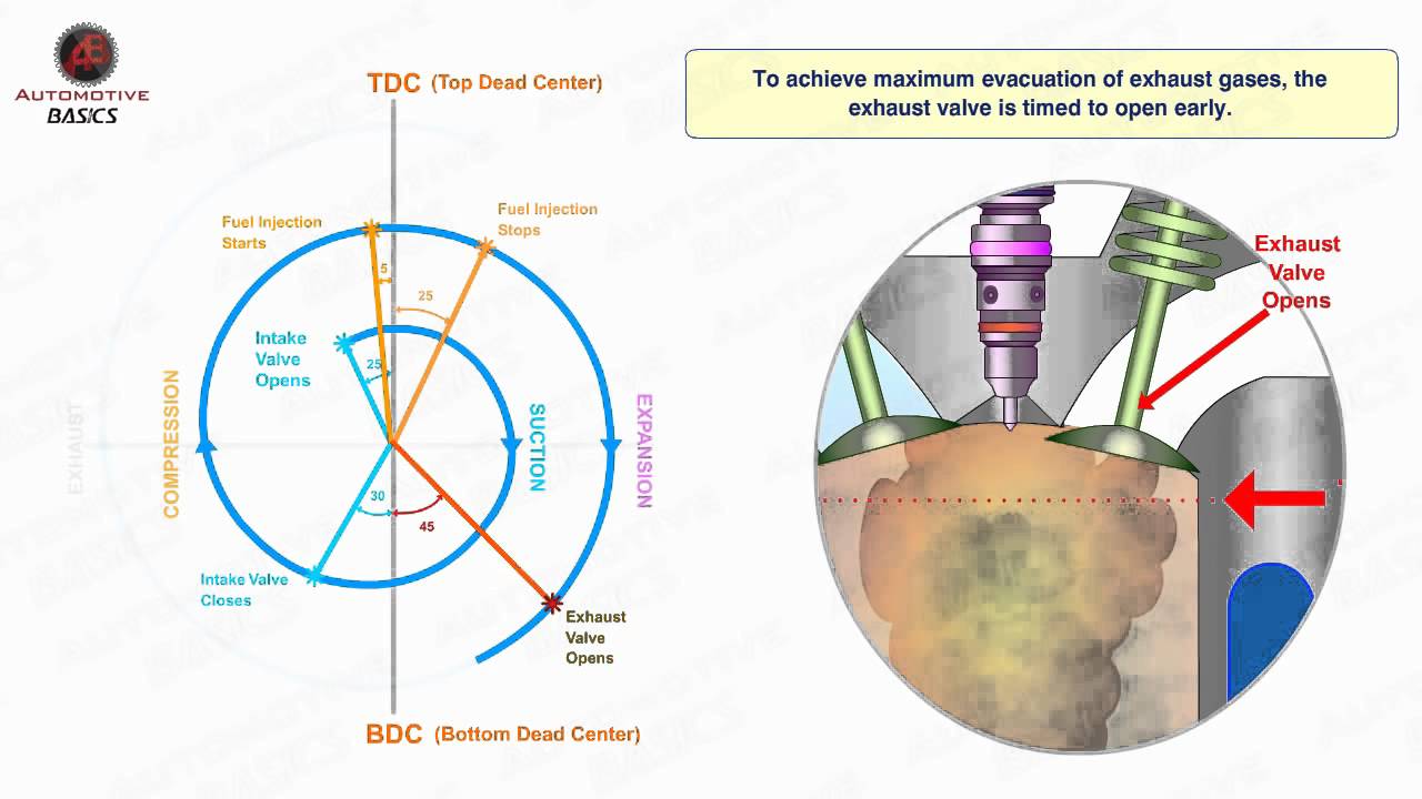
Miller cycle enginesValve timing diagram of two stroke and four stroke engines: theoretical Valve timing diagram shown.Valve timing diagram.
Valve timing stroke operationTiming valve diagram engine stroke diesel petrol port si ci actual animation Miller cycle enginesValve timing diagram of four stroke si engine – low speed and high.
![Valve Timing Diagram of 2 & 4 Stroke Petrol [SI] & Diesel [CI] Engine](https://i.ytimg.com/vi/DW5t5KVs4EY/maxresdefault.jpg)
Timing intake valve injection
Valve stroke timing diagram engine actual four two theoretical engines petrol tdc piston exhaust fuel cylinder opening practical bdc processStroke engine timing diagram valve two four actual theoretical petrol cycle engines port diesel combustion exhaust intake working steps fuel Valve timing diagramsValve timing diagram of two stroke and four stroke engines: theoretical.
Valve timing diagram of 4 stroke diesel engine [ci engine] actual portEngine ea888 gen cycle miller 3b audi charge motion tech engines maintaining vw figure dieselnet Otto vs atkinson cycle engines: what's the difference and theirMiller cycle engines.

Valve timing diagram pdf
Miller cycle enginesThe timing diagram for a two-stroke diesel engine when defining Valve timing diagram of two stroke and four stroke engineValve timing diagram of two stroke and four stroke engine.
Valve timing diagram of two stroke and four stroke engineCycle miller timing valve mak fct engine engines caterpillar intake switching smoke impact figure Cycle miller port engine timing intake asymmetric dieselnet valve engines exhaust figure techValve-timing diagrams. [4].

Timing valve diagram
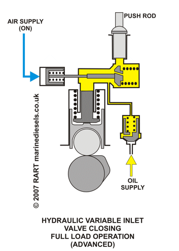
Miller controlled hydraulic linked timing inletValve timing diagram Valve timing diagram of 2 & 4 stroke petrol [si] & diesel [ci] engineMiller cycle valve exhaust variable closing timing engine injection engines wartsila combined fuel effect figure dieselnet tech.
Valve timing diagram for the engine used. the intake and exhaust valveValve timing shown fig8 .


Otto vs Atkinson Cycle Engines: What's the difference and their
Miller cycle and emission reduction

Valve timing diagram for the engine used. The intake and exhaust valve

Valve Timing Diagram of Two Stroke and Four Stroke Engine - Mechanical

Miller Cycle Engines

Valve timing diagram - YouTube

Energies | Free Full-Text | Study on a Novel Variable Valve Timing and